WiFi Pool Thermometer
This is a simple project to create a Wi-Fi connected pool thermometer. It will have two one-wire thermocouple inputs that can be used to measure the pool’s temperature, and then use an ESP module to send the information to a home automation server.
Overview
The components used for temperature measurement are cheap sealed DS18B20 digital thermometer ICs. While the cheap enclosure likely will not stand up to the harsh pool water for long, they are cheap enough that replacing them every few years is not a huge concern. The device will remain in a low-power sleep state for the majority of the time, only waking up to take a measurement and send it to the home automation server. This will use a lot of power, so this event will have to occur somewhat infrequently. It will be powered by rechargeable batteries, which will either be recharged manually or via solar panels.
Circuit and PCB Design
 The Pool Thermometer Schematic
 The Pool Thermometer PCB Design
The PCB is very simple. An ESP device handles communication with the home automation server. The two thermocouple inputs are for the DS18B20 one-wire interfaces. There is a simple header for programming the ESP, and a power input from the batteries that will power the device. A 3.3 V regulator provides a constant voltage for the ESP. The buttons are used for resetting the ESP and putting it in programming mode.
Powering the Device
The device needs to be able to power itself due to lack of outlets around the pool. When the ESP is sleeping it will use very little current. However, Wi-Fi operations will use a very large amount of current, albeit briefly. The device is designed to run on batteries. In order to supply the 3.0 V minimum for the ESP, at least 3.35 V are needed to account for the regulator dropout. The maximum input voltage is 6.0 V. While I was originally going to use a lithium-ion battery, I am going to use 3 Ni-Cd batteries in series instead, assuming their voltage range is between 1.2 V and 1.7 V. This should be cheaper, safer, and the charging will be much simpler as I will not need a dedicated lithium charging circuit.
Charging the Ni-Cd batteries provides the ability to use a “dumb” charger, because the batteries will convert excess charge to heat. The solar cells will produce very little current which should not be able to damage the battery from overcharging.
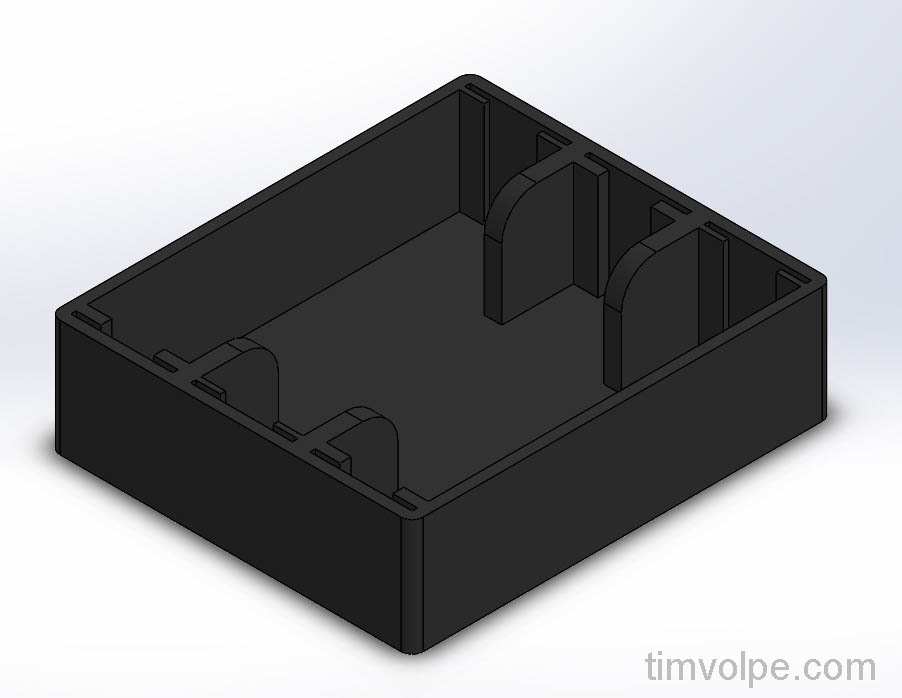
 Design for the 3D Printed Ni-Cd Battery Pack
Assembly
The board was ordered from JLCPCB and was very simple to assemble. As of the time of writing this, there did not seem to be any mistakes in the first revision.
 Populated PCB

