WiFi Pool Pump Controller
The idea for this project is to create a WiFi-controllable switch for the pool pump at my house. The device needs to be able to switch the two 15 A live wires running to the pool pump.
There are many available solutions on the market for switches that can be controlled over WiFi, but there are two main conditions that prevented me from using one of them. The first being that most switches are either designed for low current use, or claim to be rated for high current but upon inspect are unsafe to operate at these conditions. Many will not even switch a full 15 A at mains voltage. The second is that the pool pump is powered by a multi-wire branch, with two 15 A breakers joined together. This means that each hot wire needs to be switched at the same time. I have yet to see a product designed for this purpose. And of course, designing one myself is more fun.
Overview
This project is one of the most difficult that I have embarked on so far, because of the dangerous operating conditions, and the many failure modes that could have significant ramifications. For one, up to 30 A could be flowing through the system at any given time, and the load is an inductive motor with an unknown transient response on startup and shutdown. Additionally, each hot wire is operating at 115 volts, so spacing of the traces and size of the PCB will become a problem.
The core elements of the device are an ESP8266 WiFi controller, and a large 30 A relay rated for mains voltage and for use with inductive loads. The relay has two poles, one for each hot wire. The neutral wire and ground wires won’t be switched for safety reasons. It is also normally open, so that the default state of the device is powered off. The low voltage elements will be powered by an off-the-shelf AC-DC converter, because it is simpler and safer than trying to design and fit one on the already-crowded main PCB.
My goal is the mount the entire thing in a 3D printed enclosure. If airflow and heat are a problem, I have left the option available of mounting a small fan.
Schematic
 Controller Schematic
PCB Design
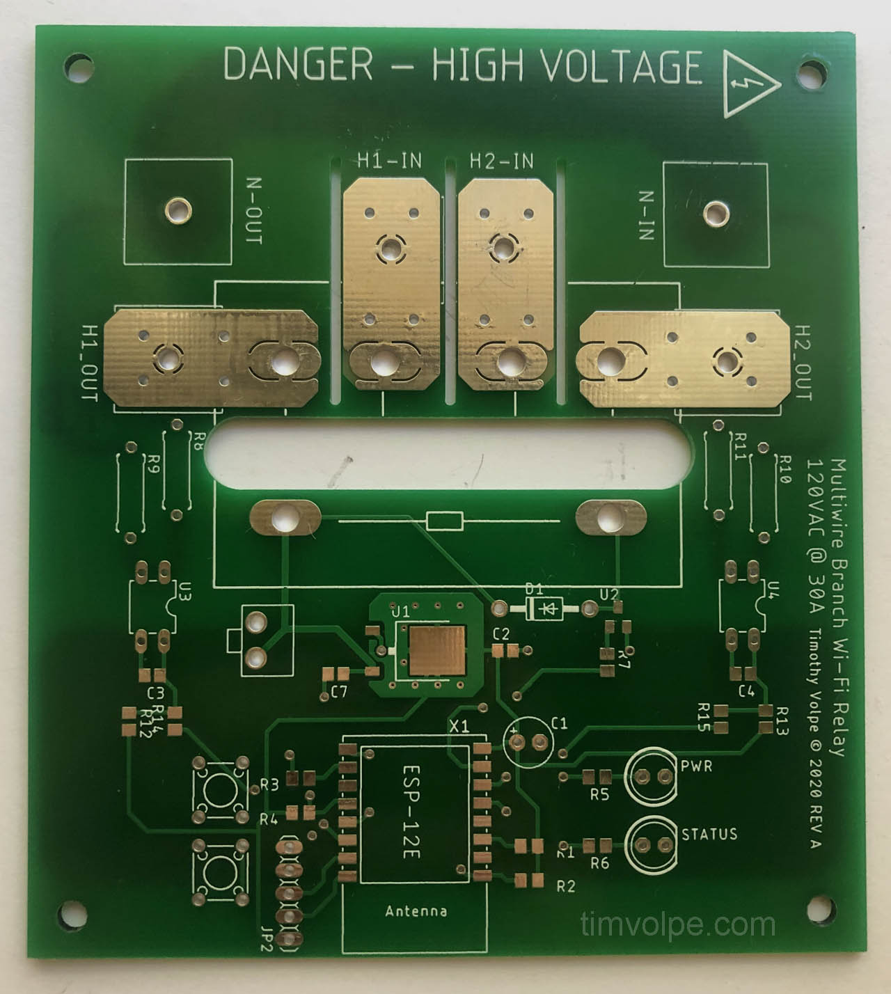
 Controller PCB
The green pours represent the mill layer, where the manufacturer should mill out that part of the board. This is to prevent creepage between the high-voltage traces. I tried to keep the traces at least 5 mm apart in all places, but where I couldn’t do this I had slots milled. Additionally I added a large slot between the high- and low-voltage parts of the board. Only at the optoisolators do the high-voltage traces cross this slot, and this is only after large resistors to drop some of the voltage and limit the current in the case of a short. The traces are sized to handle the 15 A of current, however in order to add extra headroom while keeping costs down, I had the traces exposed with no soldermask covering them, and then added solder by hand to each side. This should be more than enough cross-section to allow 15 A to flow without generating too much heat.
The low voltage side contains a linear regulator to step the 12 V down to the 3.3 V required for the ESP. This is a large drop, and the ESP can pull quite a lot of current, so the regulator will sometimes be operating close to its safe limit. However, the ESP should not be drawing maximum current for extended periods of time—only when it is performing wireless operations. This, combined with the large copper pour underneath the regulator, and the fact that the device should still theoretically be able to supply the maximum current needed indefinitely, leads me to believe it will be okay.
Two LEDs are used as status indicators. One for power and one for the state of the relay. Different blink states are used to convey other information. The two push buttons are used to reset the ESP, and put it into program mode.
As of the time of writing this I had already ordered the PCB, and one thing that I realized I had forgotten is pull-down and pull-up resistors on the LEDs and relays. Rookie mistake, however I was able to add them after the fact. It was really only important for the relay, so that it does not switch during the ESP reset.
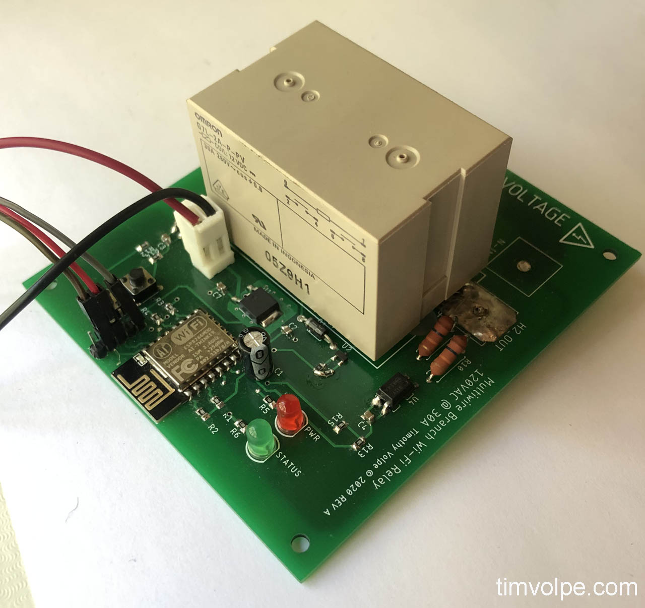
The last major components on the board are the optoisolators. These will be used to verify that the relay has successfully engaged. If, for whatever reason, one of the hot lines does not engage correctly (I am unsure if this is even possible without knowing the internal construction of the relay), the optoisolators should detect this and shut off the relay. I used the wrong footprint for the optoisolators I purchased (I accidently purchased SMD ones when I needed through-hole), but luckily they still fit and soldered correctly.
 The Blank PCB From JLCPCB
 The Assembled PCB
In the above picture you can see another mistake: the footprint for the through-hole resistors was too small, so they had to be installed slightly inclined.
Enclosure
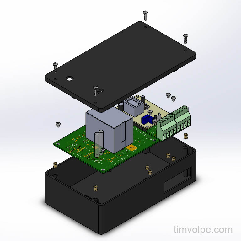
I intended to 3D print the enclosure out of PLA. I was originally going to use ABS, but I was concerned it would be too hard to print such a large box with ABS plastic, and the flammability of ABS seemed unideal. Even with PLA, printing the enclosure will be challenging due to its size, as the large flat base will want to warp during printing. I purchased screw inserts designed for use in 3D prints, which are inserted into the plastic by heating them up with a soldering iron and pressing them in. This way, I can mount the PCBs to the enclosure without having the mountings screws exposed on the outside of the box (so if they were to accidently short to the live wire, they would not be able to be touched).
While a grounded metal enclosure likely would have been safer, the cost would be significantly increased from the PLA enclosure.
The two transparent tubes visible next to the relay are light pipes for the LEDs, since they will be so far from the top of the box. I will either purchase some or create my own, perhaps with a resin in a mold, or using something as simple as a hot glue stick.
 Controller Assembly Designed in Solidworks
Programming the Microcontroller
The microcontroller was programmed using the Arduino IDE. I wrote a simple library to handle the communication protocol which can be reused for other ESP devices I make in the future. When the device is reset, it attempts to connect to a WiFi network. The last-used SSID and password are stored in the flash memory, so they are retained even after reset. This allows the device to remember the WiFi credentials. However, when the device is first used (or in the future if the user wants to change the WiFi network) it will not have any saved credentials Therefore, the device must host its own WiFi access point, have a device connect to it, and then that device set the new WiFi credentials.
After successfully connecting to WiFi, the device periodically waits for discovery requests. When a discovery request is received, it responds with the device’s information, including unique ID. This information, along with the device’s IP from the response, can be used to send the device commands. Every command must contain the device’s unique ID, or the command will be ignored. This is to prevent another device from leasing the old IP and receiving erroneous commands.
The commands that can be sent to this particular device are the relay set and reset commands, which control the relays state, the toggle command, which calls either set or reset based on the current state, and the get state command, which responds with the current state of the relay.
The device has some safety features to prevent the relay from acting unexpectedly, or in a dangerous manner. If anything unexpected happens, such as a memory issue or the optocouplers reading the wrong state, the device faults and must be manually power cycled. While this is detrimental to the user experience, it acts as a fail-safe to force the acknowledgment of a serious error. The device always defaults to the open relay state, and a timer is put in place to prevent the relay from toggling state too quickly.
The code for the microcontroller will be available on my [GitHub].
User Interface
The user is able to interface with the device via a computer program. I wrote a Python library which communicates with the device itself, so a program can be written using this library to provide an interface. In my case, I decided to write a Home Assistant plugin that interfaces with the device, allowing me to add it to my Home Assistant server running on a Raspberry Pi.
The code for the interface library and the Home Assistant plugin will also be available on my GitHub.

