Candle Game
For one of my lab finals the task was to create a simple “game” that must include components from a predefined list. The game was a candle that could be “ignited” and then “blown” out.
Overview
The circuit had to include a minimum number of components, including diodes, transistors, and op amps. The circuit that I devised included a number of these components and satisfied all the project requirements.
The way it works is the candles are ignited by holding down the “ignite” button. The longer the button is held down, the more candles “ignite.” Then, the player can blow the candles out by blowing on the microphone.
Schematic
 The Candle Game Schematic
The circuit is powered by 5 V, intended to be powered by an external power supply or a bench power supply. There is a toggle switch to control power to the board. An LED indicates when power is on.
The game starts when the player holds down the ignite button. Holding down this button begins to charge up a 470 uF capacitor, C1 through a resistor. As the capacitor charges, the voltage across it increases and is compared to the voltage across three potentiometers. The first candle is ignited as soon as the button is pressed and does not need a comparator. These potentiometers allow the player to adjust how long it takes for each candle to ignite when the button is pressed. The op amp comparators then send a digital signal to a CD4043B quad R/S latch. This latches the candles in the “ignited” state.
The game is then played when the player begins to blow out the candles. The microphone is connected to an amplifier, which increases the small signal produced by the tiny electret microphone. This is then fed to an op amp which compares its voltage level, determined by loudness, to a set value defined by a resistor divider. If the voltage is above this level, the op amp output goes high and begins to charge a capacitor, C7. This capacitor is designed to discharge quickly, so that if the player stops blowing their “progress” isn’t saved. The voltage across the capacitor is when compared to values defined by Zener diodes, and the reset pin on the CD4043B latch is switched high to “extinguish” each candle.
There is a reset button to reset all the candles to the off state.
PCB Design
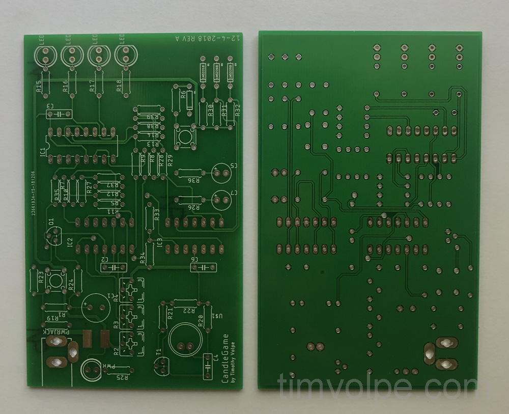
 The Candle Game PCB
 The Blank PCB Manufactured by JLCPCB
The PCB design had very few significant challenges. All of the components are through-hole, resulting in a relatively large board. The LEDs were placed in a row to simulate candles. Pads for the on-off switch are large so that wires can be soldered to them for the external toggle switch.
The microphone circuit is kept separate from the rest of the components to keep the noise from interfering with the digital functionality, although this seems unlikely to occur.
Assembly
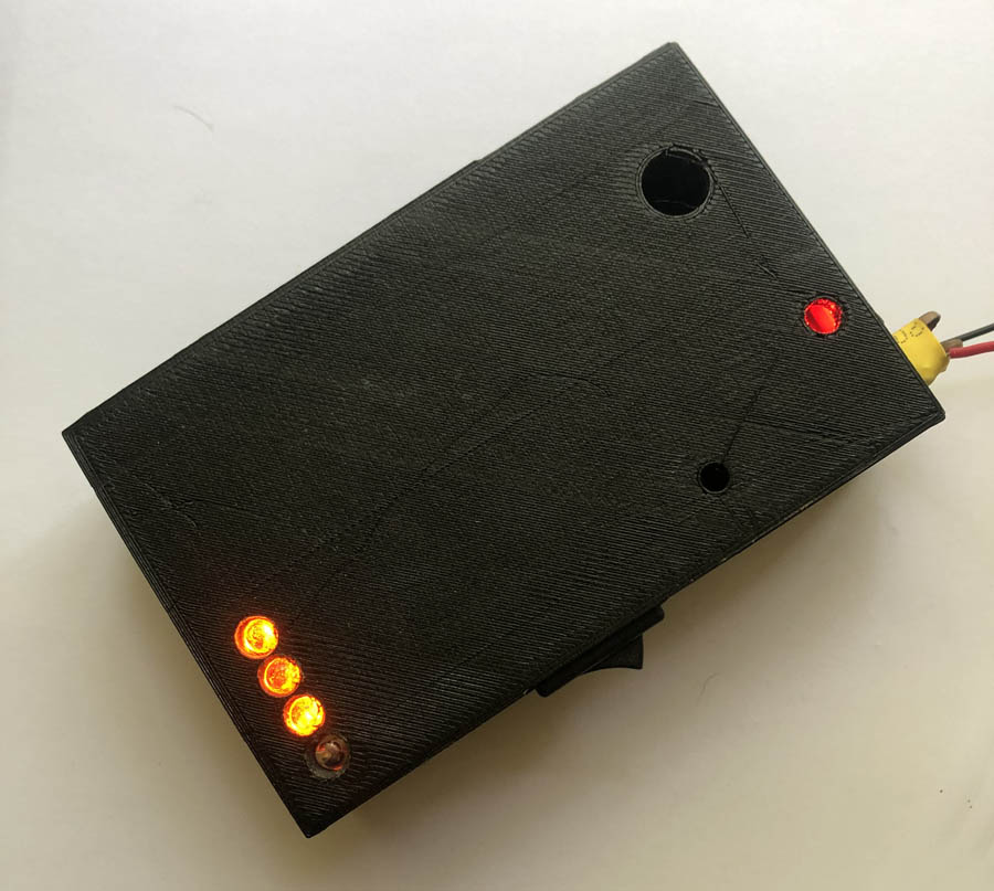
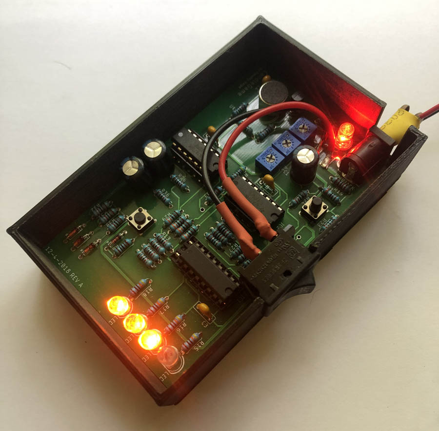
 The Candle Game Assembled in 3D Printed Case
The board was manufactured by JLCPCB and hand soldered. A 3D printed case was created to house the board to provide a better user experience. Unfortunately there were problems with the print warping on the print bed due to its size, but the final product was relatively straight. The LEDs don’t precisely fit in the holes created for them, and push buttons for the PCB mounted tactile switches were never printed due to time constraints.
Chip sockets were used at the request of the instructor to prevent damage to the chips during soldering, and to facilitate the replacement of any dysfunctional chips in the future.
Conclusion
 The Candle Game With Lid
 The Candle Game Without Lid
The game worked as expected on the first revision. The only major problem was the sensitivity of the microphone and amplifier circuit resulted in the first candle being extinguished by the sound of the button being released. This could easily be fixed by changing the sensitivity, or moving the button away from the microphone.

