Making Use of Cheap Solar LEDs
I have a bunch of old, defunct, cheap solar LEDs from Harbor Freight that when working at their full potential, produce barely enough light to be visible. I am going to attempt to disassemble them and see if any minor improvements can be made to make them more robust and useful, or if the components can be used for something more interesting.
Overview
The devices themselves are meant to be used outside. During the day, the sun charges up a small 1.2 V Ni-Cd battery, and at night this is used to power the LED. The LED is a tiny RGB LED that fades between different colors. One of the biggest problems with these lights, besides their lack of light production, is the fact that they are not weatherproof. Most of the boards have water damage, ranging from minor corrosion to severe flaking-off of the copper and breaking of the connectors. The plastic shapes that sit on the LED to diffuse the light become brittle and crack within a few months of being outside.
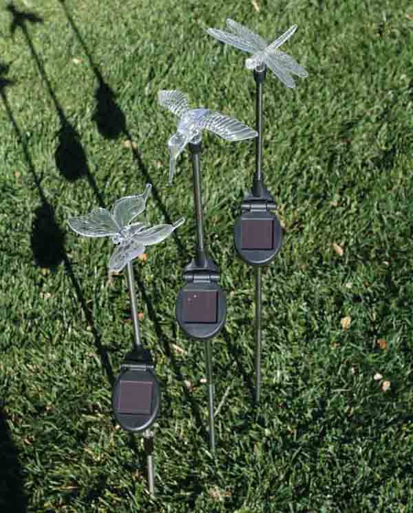
 Solar LED Lights sold by Harbor Freight
Reverse Engineering the Circuit
The first step I took was to dissemble a device and reverse engineer the simple board inside. This was fairly simple as there are only 5 components. The device, as expected, was shockingly cheap in its construction.
 Reverse-Engineered Solar LED Circuit
The core of the circuit is a QX5252 solar LED driver IC. There is a switch on the board, whose position according to the markings on the plastic represent “OFF” and “AUTO.” When it is in the “OFF” position, the switch is just an open circuit. The pin is not even soldered to the board; neither are the mechanical reinforcement pins on the switch housing. The rest of the circuit is an axial inductor for the driver IC, a Schottky diode to prevent destruction of the device if the battery is put in backwards, and the LED and capacitor. I’m not entirely sure on the purpose of the capacitor, perhaps it is smoothing the voltage, but the battery should provide a stable output. The LED is a self-changing RGB led, so the circuitry for fading between colors is inside the lens.
The QX5252 IC is connected to the battery and to the solar cell. According to the datasheet, an external inductor is required for the circuit. The datasheet provides very little information but it seems as though some kind of switching regulation is occurring involving the inductor, as there is a graph showing frequency vs. inductance. Many of the devices have different values of inductor in them, one I took apart showed a 200 uH inductor, and another showed a 63 uH inductor. Unfortunately I have no way of measuring the inductance so these are only based of the markings which are faded and hard to read in some cases. But it seems as though the inductance value has a very large margin, and they probably used whatever component was available cheapest at the time.
The IC claims to regulate the LEDs power based on the inductance and the battery voltage. With the TO-94 package that is in these devices, the solar panels output is used to control the status of the LED in the “AUTO” mode.
Harvesting Components
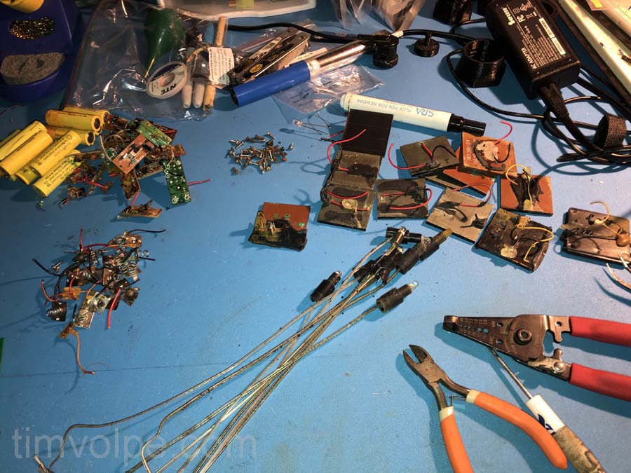
 Harvested Ni-Cd batteries, boards, LEDs, and solar panels (plus screws and battery terminals).
I removed the circuit board, LEDs, solar panels, battery contacts, and Ni-Cd batteries. The contacts can be used in other projects with 3D printed enclosures. Most of the circuit boards are completely destroyed by water damage, with their components disintegrating in my hands. Some of the solar panels unfortunately were too hard to remove and the wires got lifted from the panel. It may be possible to reattach them with some kind of adhesive.
The Solar Panel
The solar panel is the component of most interest to me. Held up to a desk lamp, the panel produces about 2.0 V across it as measured with a multimeter. I connected a 430 Ohm resistor across the leads and put the LED in direct sunlight. It produced 2.5 V across the resistor, so about 5.8 mA, or about 14.5 mW. This is about what I was expecting. I intend to take multiple panels and try to combine them in series or parallel and see what kind of output I can get.

