Christmas Tree Ornament
I wanted to create a cool ornament for the Christmas season using my electrical engineering skills, so I decided to create a Christmas-tree shaped PCB.
Overview
The idea is very simple: a battery-powered ornament that will last for a reasonably long time, and is interesting to look at. I decided to create a PCB in the shape of a Christmas tree because I had seen other similar projects and though the style was fun. The core of the ornament is an ATtiny25 microcontroller, because it is low-powered and small but has enough pins to get the job done. The tree will have various LEDs that light up.
Schematic
 The Christmas Tree Schematic
There are two ICs on the board, the ATtiny25 and a SN74HC138 3-to-8 demultiplexer. The purpose of the demux is to have more controllable LEDs than the ATtiny25 can handle with its limited number of pins, but more importantly, to utilize persistence of vision to save power by only toggling one LED on at a time. The microcontroller will be programmed to quickly switch between LEDs to display patterns of one or more LED, which can be altered by reprogramming the board.
The board contains 8 LEDs which all share one resistor, since only one LED can be on at a time. The demux is sinking the current from the LEDs, as the SN74HC138 will set the selected output to low, and all the others will be high. When the enable pins are high, all of the outputs will be high.
The board is powered by a CR2032 coin-cell, which operates around the 3 V that will power the ATtiny25. A diode protects the board from reverse-voltage.
There is a single button on the board tied to the reset pin of the ATtiny25. The intention is that every time the board is reset, it will display a pattern for a short period, then go to sleep. That way, the reset pin will display the pattern but also reset the microcontroller.
PCB Design
 The Christmas Tree PCB
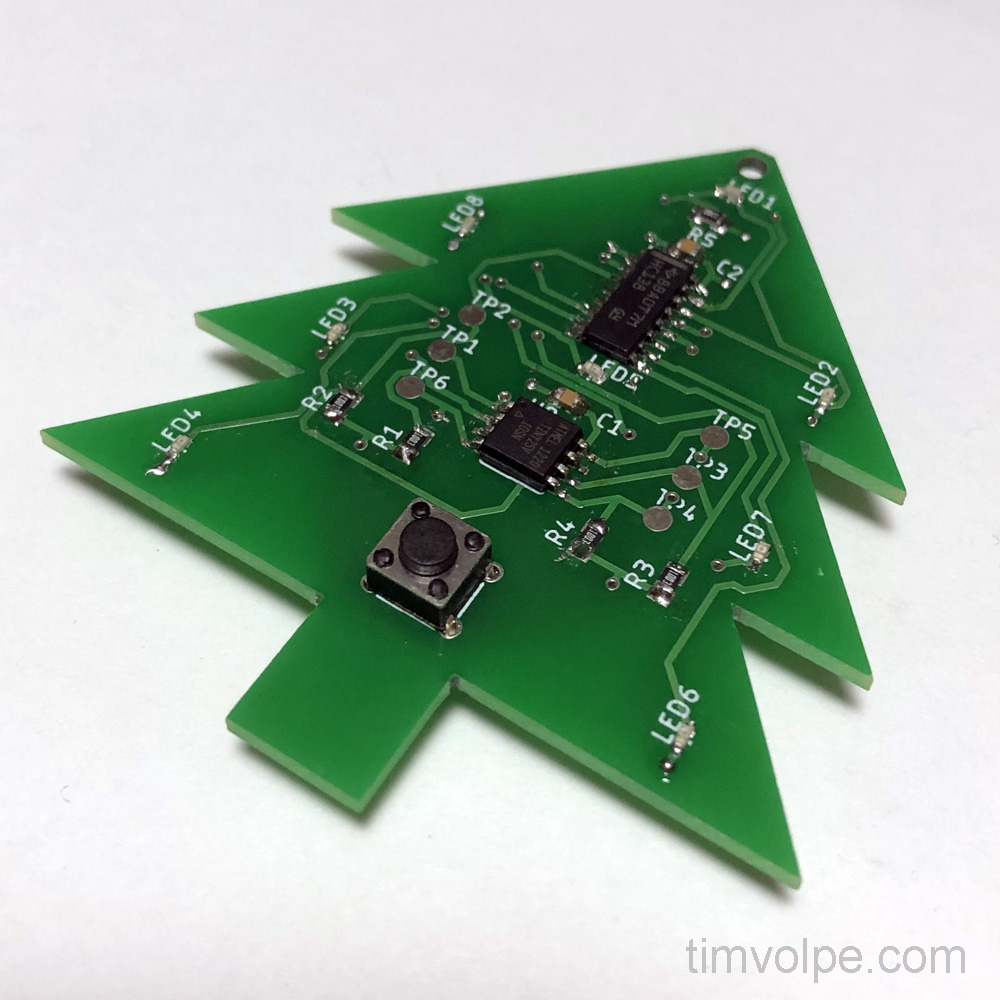
The PCB is designed to be in the shape of a Christmas tree. The LEDs are present at the end of the “branches,” as well as in the middle and at the top. The other components can be found in the middle, making up the “trunk.” The button is also on the bottom-middle. Routing the board was tough due to the small size, but in the end it turned out to be efficient and compact. The coin cell is found on the back of the board to hopefully hide it from view.
 The Manufactured PCB With Soldered Components
There is a small hole at the top for hanging the tree. Additionally, there are test points for pogo pins, which are talked about in the next section.
Programmer
 The Christmas Tree Programmer CAD Model
One of my hopes for this project was to test out the use of pogo pins for programming without needing ugly headers. There are 6 test points on the board that can be used as contacts for these pins, to program the board. I created a 3D printed fixture to house the pogo pins that the board is pressed down on top of for programming. An USBasp is plugged into this fixture for programming, which can supply its own power, or use the board’s power from the coin cell.
 The Christmas Tree Programmer
Something I learned here is to make sure that the test pads line up to a standard 2.54 mm grid if you want to use a perfboard for the fixture! My pogo pins do not line up, which results in some ugly "surface mount" pogo pin soldering.
Program
The program was written in C using the WinAVR package of avr-libc. It allows simple, pre-programmed sequences to run every time the user presses the reset button. Since there are 8 LEDs on the board, each controlled individually by the 3 demultiplexer inputs, an entry in the sequence can be defined by a single 8-bit integer where each bit represents an LED. Then, each bit position can be tested, and the LED can be turned on using a map to convert between LED index and demultiplexer input.
While the sequence can theoretically be very long, I chose to use 16 entries. There are multiple types of “delays” to properly construct the pattern visually. First, there must be a delay for persistence of vision, as only one LED can be physically on at a time. This delay must be long enough so the LEDs appear sufficiently bright, but short enough that flickering isn’t apparent. Additionally, the MCU’s clock speed will reduce as the battery voltage drops, so flickering must not appear as the battery drains. DELAY_LENGTH defines the length of this delay, which is created with “nop” instructions and is dependent on the clock speed.
A second delay must occur to “hold” the current sequence index before transitioning to the next one. This is defined by PERSIST_REPEAT_COUNT, and is the number of times the 8 LEDs are looped through to maintain the visual effect of having multiple on at once.
Finally, the entire sequence repeats PATTERN_REPEAT time after the user presses the repeat button. After this limit is reached, the CPU goes into sleep mode until it is reset again. The demultiplexer is disabled to turn off the LEDs.
Below is the code:
/* When reset, device displays a short light pattern, then goes into sleep mode Device is awoken by reset. Demultiplexer drivers the LEDs LED1 = Y0 LED2 = Y1 LED3 = Y2 LED4 = Y3 LED5 = Y4 LED6 = Y5 LED7 = Y6 LED8 = Y7 SN74HC138 Inputs A = PB0 B = PB1 C = PB2 G1 (ENBL) = PB3 ; Logic Table (When enable is high) ------------------------------- | C | B | A || LEDX | Index | ------------------------------- | 0 | 0 | 0 || LED1 | 0 | | 0 | 0 | 1 || LED2 | 1 | | 0 | 1 | 0 || LED3 | 2 | | 0 | 1 | 1 || LED4 | 3 | | 1 | 0 | 0 || LED5 | 4 | | 1 | 0 | 1 || LED6 | 5 | | 1 | 1 | 0 || LED7 | 6 | | 1 | 1 | 1 || LED8 | 7 | ------------------------------- */ #include#include #define PIN_SEL_A 0 #define PIN_SEL_B 1 #define PIN_SEL_C 2 #define PIN_ENBL 3 /** t_delay = (4 clocks) * (clock period) * DELAY_LEN NOTE: the clock speed is going to change significantly as the batteries drain. At 2.7 V, the maximum frequency is 10 MHz, whereas at 1.8 V it is 4 MHz. 10 MHz = 0.1 us * 4 = 0.4 us per delay (max = 102 us) 4 MHz = 0.25 us * 4 = 1.0 us per delay (max = 255 us) */ #define DELAY_LENGTH 150 /** The number of time to loop through the active LEDs, "holding" multiple LEDs on at once. */ #define PERSIST_REPEAT_COUNT 150 /** The number of times to repeat the pattern before going to sleep */ #define PATTERN_REPEAT 10 int LEDIndexMap[] = { 0b000, 0b001, 0b010, 0b011, 0b100, 0b101, 0b110, 0b111 }; int SequenceMap[] = { 0b10100110, 0b01011000, 0b00101110, 0b01010101, 0b01101001, 0b10010110, 0b01100010, 0b10101010, 0b00010110, 0b01010100, 0b00011011, 0b10010100, 0b00101001, 0b01111110, 0b10011001, 0b00000000 }; #define SEQUENCE_LENGTH sizeof(SequenceMap) / sizeof(int) void set_led(unsigned char led_index); void persist_delay_cycles(unsigned int delay_cycles); void setup(void) { DDRB = _BV(PIN_SEL_A) | _BV(PIN_SEL_B) | _BV(PIN_SEL_C) | _BV(PIN_ENBL); PORTB = 0; } int main(void) { int i, sequence; int pattern_repeat; int repeat_count; int sequence_index; setup(); for( pattern_repeat = 0; pattern_repeat < PATTERN_REPEAT; pattern_repeat++ ) { for( sequence_index = 0; sequence_index < SEQUENCE_LENGTH; sequence_index++ ) { // Set the sequence pattern // Grab sequence bits sequence = SequenceMap[sequence_index++]; // Set each LED for( repeat_count = 0; repeat_count < PERSIST_REPEAT_COUNT; repeat_count++ ) { for( i = 0; i < 8; i++ ) { if( (sequence & _BV(i)) > 0 ) set_led(i); persist_delay_cycles(DELAY_LENGTH); } } } } PORTB = 0; sleep_enable(); sleep_cpu(); } // declaration and for loop adds some extra but constant delay void persist_delay_cycles(unsigned int delay_cycles) { unsigned int i; for( i = 0; i < delay_cycles; i++ ) asm volatile ("nop"); } void set_led(unsigned char led_index) { unsigned char sel_vals; if(led_index > 7) led_index = 0; sel_vals = LEDIndexMap[led_index]; // Disable demux PORTB &= ~_BV(PIN_ENBL); PORTB = 0b11111000 & PORTB; PORTB += sel_vals; // Enable demux PORTB |= _BV(PIN_ENBL); }
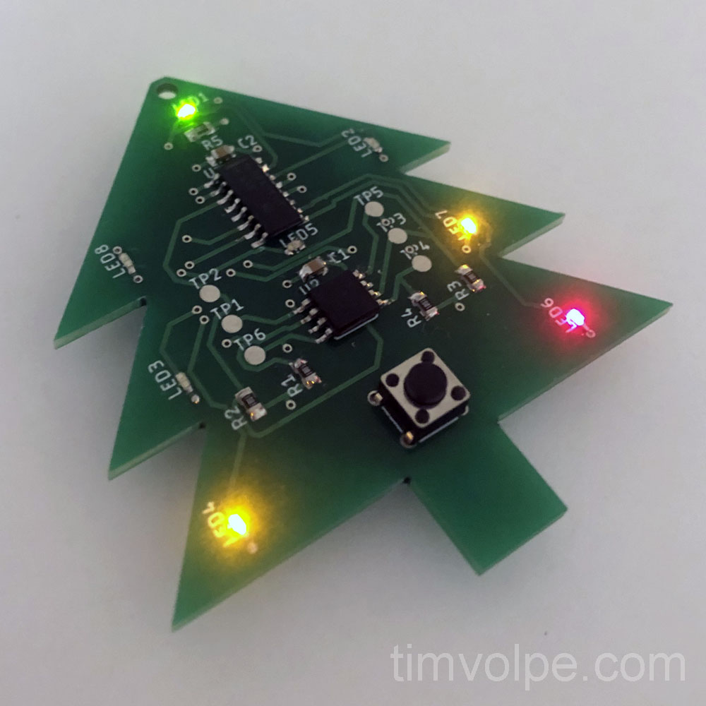
 The Christmas Tree Lit Up
Conclusion
Overall the project was simple and worked well. In hindsight, I should have placed the test points for the programmer better, making them line up with the protoboard holes. Additionally, the complex shape of the board, coupled with the poor tolerance of the 3D print due to shrinkage made the “hole” for the board extremely difficult to measure and size. In the end, I had to chip away at the edges to get the board to fit snugly.
Despite this the boards themselves came out perfect and make excellent gifts.

